Using Valve Hammer Editor to Create Worlds for
![]()
The Valve Hammer Editor is copyright
2001-2002 by Valve LLC, Michigan Detroit, U.S.A. All rights reserved.
Half Life, Half Life Counter Strike, and other mods are copyright © 1997-2002
by Valve LLC. All rights reserved. This page is (C) 2003 -2004 amckern -check legal for details
Last update 9th July 2004
Welcome to the Valve Hammer Editor (hammer /wc) overview and tutorial. Hammer is the tool created by Valve that enabled the Half Life community Level Designers and Artists to create the geometry and game play you experienced in Half Life, or one of its MODs. Hammer allows you to build the ground, sky, walls, ceilings and shapes for your levels. You will then apply textures, props, prefabs, lights and sounds to give them a realistic appearance. Half Life was created using literally thousands of these assets which you may appropriate to create the base for your own level. You may also add your own assets where applicable. Finally, you 'll add the game objects that allow other players to interact with your world.
Creating levels is an extremely complex and time consuming process, and the following is merely the starting point for those who want to learn the basics of building worlds for the Half Life engine. If you 've done game design before on a 3D or near 3D game, you 've probably worked with tools like Hammer.
I will start with a index, because this page is over 75 pages to print.
Basic
Terms
Building
Your First World
Making a Simple Room, and your
first map
Knowing what to put into
a map to make it work
Hammer Resource
Types
Creating
Brushes to Fit Your Needs
The Camera
More complex
brush work
Selecting Brushes
Brush Power Tools
Flipping,
and Turing Brushes
Advanced
Texturing and Alignment
Invalid Brush
Types
Working With Concave
Brushes and Loose Faces
Lighting the Map
Working
With Light Colors
Lighting
Half Life Worlds
Adding
Sky to Your Half Life Level
Advanced
ZHLT Compile Tools Use
CSG
BSP
VIS
NET VIS
Map
star
RAD
RIP
Ents
Batch
Shared
Half
Life
Types
of Compile and Their Advantages
Optimizing
Your Level
Factors
That Cause Levels to Bog Down
Troubleshooting
Visibility Leaks
Plugging Leaks
Legal
Basic Terms
These terms are relevant to a discussion of Hammer.
Map /World A map in Hammer represents the sum of all the resources in the game: all the code, all the textures, all the sounds, all the entities, and so on. When your players walk around in your game, it is a world that they 're standing in. Worlds also divide your game up into sections where different parts of the game take place. In other games, these are sometimes referred to as maps, levels, scenes, or episodes. World editing is the primary focus of Hammer and each world is stored in a separate file on the hard drive.
Entities Simply put, anything a player interacts with that moves, lights up, shoots, growls, or goes into the player 's inventory is an entity . Hammer allows you to place any kind of entity that your games code or the engines code can create.
Brush /Primitive The basic unit of world geometry. A brush is made up of planes that define its faces, lines that define its edges, and vertices that define its corners. All brushes must be convex for reasons that will be discussed later. You can manipulate either an entire brush at once or any of the vertices, lines, or planes in the brush. Typical brushes are things such as cubes, pyramids, and cylinders.
Prefab A prefab is like a primitive, but more complex. If you build a street lamp complete with textures and a light source that gives off just the right shade of light, you can select the lamp and its associated source (or any group of objects and brushes inside Hammer) and save it as a prefab . Thereafter, you can copy and paste that street lamp into your world without having to rebuild the whole object.
Unit The basis of measurement in Hammer and the Half Life engine. Units don 't equate directly to real world values. Instead, the game designers can select a scale of game units to real world measurements. As an example, in Half Life the following values are used: railings are 32 units tall, a chest high box would be 48 units, and a typical doorway would be 128 units high. Also a player crouching would be 48 units, 64 at full stand, and 96 jumping.
Processing or Compiling When you process your world, hammer creates a second version of the world with some information removed (parts only you need to know about), and other information added (parts only the game engine needs). Processing is a necessary step you 'll take in getting your world up and running in the game, and is often the first place where you will discover problems with your level.
Texture In Hammer, textures are used like wallpaper, paint, or plaster to cover the raw plywood of your walls, floors, ceilings, doors and so forth. Without a texture, your brush will appear flat shaded in the game, almost always with unpleasant results. Just as you wouldn 't want a house with raw plywood walls, you always want to apply textures to the brushes in your level.
Building Your First World
The first step well want to follow in building our new world is to set up hammer. If this is your first time opening up the Hammer, then you will be asked to use the set up guide. You can of course use this guide, though I have also supplied a Guide, to setting up hammer in full for Sven Coop.
Getting World Craft set up is the part that most people screw up at. It is hard to make any progress if you can 't even get your map to compile. Besides adjusting all the settings, you need two files. One is the sven coop.fdg file for WC. What this does is load the custom Sven Coop entities into WC. You can get this .fdg file from the root sven coop folder, named sven-coop.fgd.
The other file is ZHLT, short for Zoner 's half life Tools. You can get them here . These are programs that turn your WC file into something every other owner of Sven Coop can play. They compile the .map files into a playable .bsp file. ZHLT 's are replacements for the original half life compiling tools. ZHLT 's do the job better, faster, and prettier. Not to mention they do a lot better job of telling you where you screwed something up.
Now that you have these two files, place the sven-coop.fgd file into your WC directory, most likely C:\program files\worldcraft or something. Unzip (or install) ZHLT 's into the same directory. When you are finished, there should be a few new files in your WC directory -sven-coop.fgd, hlcsg.exe, hlbsp.exe, hlvis.exe, and hlrad.exe. (There might also be 3 new .dll files that the XP-Cagey version of ZHLT need to run -msvcp71.dll, msvcr71.dll, and stlport_vc7146.dll)
Now that you have your important files in place, it is time to enter the lair of the demon, and tame him by configuring his settings properly. This demon is called World Craft, and if he is not properly tamed, he will not give you that which you most desire, the all enjoyable Sven Coop map. If you truly bungle at taming him, and try to weasel a map from him, he may even go so far as make you a miserable wretch and crash your system into the depths of re-boot.
Start up WC. Once it has loaded, click 'Tools ' (located in the upper left corner of the screen). That will pull down a little menu. One of the items on the menu is labeled 'Options '. Click that. This will bring up the really important menu. The tab in front will say 'General '. No need to fool around with that at the moment. Click the 'Game Configurations ' tab.
Set everything to the same way I have it in these screen shots, excepting of course, where files and paths may be different on your system. The three tabs that actually matter are the Game Configurations tab, the Build Programs tab, and the Textures tab. The other three you can play around with a bit if you understand them. If you don 't, you can leave them alone and be ok.
On to the big Kahuna. The Game Configurations tab, shown here:
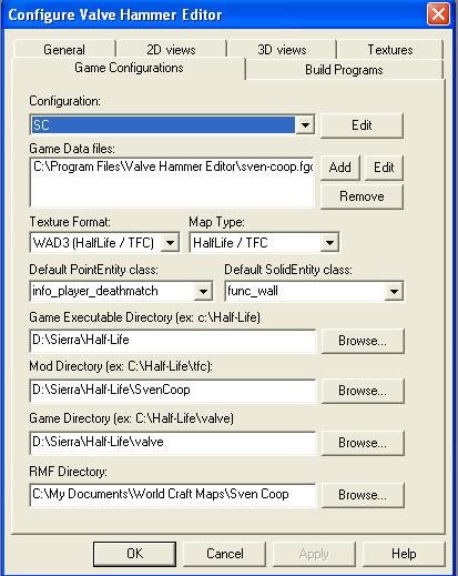
It controls all the little things that are important for WC to actually find the supposed files you are trying to compile with. Now, until you load the sven coop fdg file, your screen won 't look the same. But when you do, you should have a pretty fair approximation. Set all your variables to the same as are shown here. Excepting of course, where you have things in a different directory. (To add the SC "Configuration"Click edit, then click add, the type the name in. Once toy do that click close)
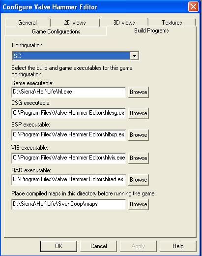
Next, the all important Build Programs tab.
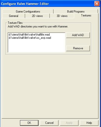
And lastly, the textures tab. Its always good, to keep the HalfLife.wad in your wad list, as this has the most useful textures, that you will use. The sc_avp.wad is a custom wad found at http: //downloads.ammahls.com /sc /maps /sc_avp_v2 /sc_avp-wad.zip , and is the wad used in the sc_avp mission set. You can also add wads from your favorite maps, or if you 're really cool, wads that you 've created on your own with Wally.
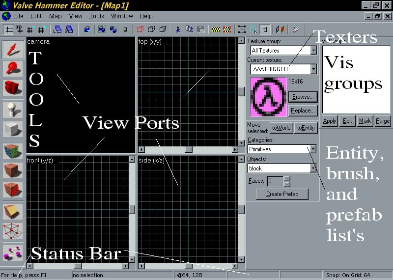
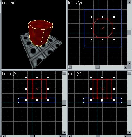
Now that your set up, go to the File menu and select New . Now hammer will open up with something that looks like this
Now click File and then Save when Hammer asks you what to name the world, type “Simple1”. This is the name your world will have when you go to open it in Hammer.
Tip: The name you provide is also the name of the worlds file on your hard drive ( Simple1.rmf ). Later we will cover how the project is written to your hard drive.
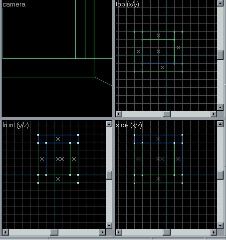
The callout 's in the above screen shot illustrate the various sections of Hammers UI. Use the buttons in the Toolbars to make new worlds, switch modes, and run your world. You can learn an individual buttons function by placeing your mouse over it to get a Tool Tip.
There are four viewpoints that provide windows onto the world you 're building. Each one presents a different view of the world. The upper left window shows you a Perspective view shot from a movable camera point in the level. The other three views have a fixed view camera that displays either Top, Front or Left view (going in clockwise order). You 'll spend a lot of time working with these views.
In the Status Bar , Hammer provides information about the level or about the view you 're currently in. We will get into the depths of the user interface in later chapters, although you 're welcome to stop and explore if you 'd like. Use the Tool Tips and the Status Bar to learn more about what the controls do.
In the Vis Groups , Hammer provides information about the Visible groups, that you have made. We will going to do this later on as well.
In the Entity, Brush, and Prefab lists , Hammer provides all the brush types, prefabs that you have made, or entities that you can place in your map.
In the Textures , Hammer shows each
image that you can use in game, along with a thumb nail of what it looks like.
Clicking browse enables you to search through each wad wad that you have set up
by key word, or by looking at each one. All images in the browse menu are show
at real size (1:1), and not thumb nail size.
Making a Simple Room, and your first map
Understanding the entities
Our first world is going to be very, very simple. Were going to make a box with a light.
Even though this level is extremely simple, well still want to texture it. Use your mouse to select the Textures list on the right hand side of the screen. This list is where you select textures to apply to your brushes. In the top section of the Textures list there is a texture named AIR_C1, if you can 't see it, scroll down the list until you find it, once you find it left click once on this thumbnail.
The drop down box should now be gone, where you had the T or A thumb nail, you should now have a thumb nail with a black circle in the middle of it.
To actually start putting brushes into your world, first move your mouse pointer over to the middle left of the screen and left click once on the block tool . you can also use shift + b as a hot key for it. Now move the mouse over to the grid. (A thing to keep in mind when using hammer is that If the view ports are your eyes, then the marker is your hand).
Now left click and drag on the grid, and
move the mouse. You should have a box expanding from where you clicked the
mouse, this box is a brush. To place the brush, right click, and chose from the
context menu "Make Object", or just press the enter key. Now if this
brush is to big, you can re size it by clicking on the x in the middle of the
brush (or one of sides of the brush), and use the drag handles to re size the
block. You will note that Hammer, has scroll bars on its view ports, these are
to move around the build grid, and they automatically scroll when you move, or
make your brush go past the side in one of these view ports.
Now that you have made your first brush, undo
it by pressing ctrl + z, or click edit, undo, in the menu 's. because i don 't
know how big you made your brush, the next room can be tricky, so undoing the
brush is worth while. The undo is also useful if you make a mistake in your
map, or a part of it looks wrong. You can undo up to 150 actions, but be
careful, as redo can cause problems in your map.
Now please get the block tool active, and
draw a box that is 4 units long, and 1 unit wide, in the top view port. make
the brush by pressing enter. Now in the side view port, click the block, and
drag it down so that the block is also 4 units tall.
Now press ctrl + c, to copy the brush, then
click any blank part on the grid, and press ctrl + z. This KISS (keep it simple
stupid), is very useful for brushes that are repditave, such as a hall. Now
align the pasted brush so that its 4 units away from the other one, in both
top, and side views.
Build an other brush, this time in top view
that is 4 units wide, and 1 unit thick, and make it 4 units tall in side view.
Do the same as the last wall, and copy, and past it, so that you have an open
cube that looks like this:

Next build a brush from the top left hand
corner, in top view, to the bottom left corner. Align this brush to the top of
your open cube -this will be your roof. Copy, and past this brush, then align
it to the bottom of the cube, to make the cube -this is your ground, and now
your cube is closed in.
The end result should look like this:
This is the basics for your first map. You
have your map, now its on to adding the entities, that make the map playable.
Knowing what to put into a map to make it work
Now we reach the step where we put the things in the map needed to make it work. It 's only 5 things. Real simple.
Let 's start with the first -a light . Can 't really play if you can 't see. Notice the absence of maps titled 'sc_pitchblack '. The light is an entity in hammer. So, click the entity tool or use the hot key shift + e . Left click the middle of your room with the entity pointer. Move it around if need be, until the entity box is near the top center of your hollow box. You may have to zoom in a bit to see what you are doing (magnifying tool -left click to zoom in, right click to zoom out). When the entity box is where you want it, place your cursor (with the entity tool still selected) and right click it. Select 'create object ', or press enter. Now you have an entity in your box. But, most likely, it 's not a light, unless you selected that as the default entity to use when setting up Hammer. Click the selection tool. Highlight the entity box by left clicking it. It will turn red. You may have to zoom in to select it. Left click any blank area to de-select something if you 've selected it by accident. Now that you have the entity box highlighted, right click the little purple entity box, and select 'properties ', or use the hot key alt + enter , from the menu that comes up. This will give you a fascinating dialog box that looks like this:
In the top pull down menu, scroll down until you see an item labeled 'light '. Select that. It will have a few options that come with it -target, name, ect. The one we want is 'brightness ' Click on that, and the value box to the right of it will show 4 sets of numbers that look like this '255 255 128 200 '. The first three control the color, in hexadecimal format. The last one controls the brightness. Change it to 900 as we want a pretty bright light for this level, as it will be the only light we are going to have. Close the dialog box. Now you have your light.
Next, we put in a spawn point. A spawn point is where you start at the beginning of a round. The player spawn points are also entities in Hammer. So, click the entity tool again, and place two entities on the bottom of your cube, on opposite sides. Go through the same steps as we did for the light, but instead of selecting 'light ' in the properties box, select "info_player_deathmatch"for a the spawn point. This confused the heck out of me at first.
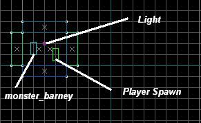
Now you have your spawn point, lets place a NPC. This NPC Will be Barney.
So use the entity tool again, and browse to the "monster_barney"and place him next to your player, so it looks like the above screen shot
Now you have your room, a light, a Spawn
spawn point, and something to kill. Let the compiling begin.
Click file, then save, to save the map, as
compiles only work of saved work, then Hit F9. This will bring up the
compile dialog box. Click advanced, in the drop down list on the top left,
chose counter strike full and you should have something that looks like this:
(If your box has not got any "Additional Game Parameters"then fill it
out as you see in the screen shot)
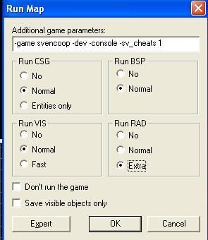
Click go, or press enter, the compile will take up to 30 min (maybe more) depending on the computer system you are running. It might look like hammer has locked up, but don 't shut it down. The compile tools are hungry for CPU power, and screen refreshing in hammer is the last thing they want your computer to do.
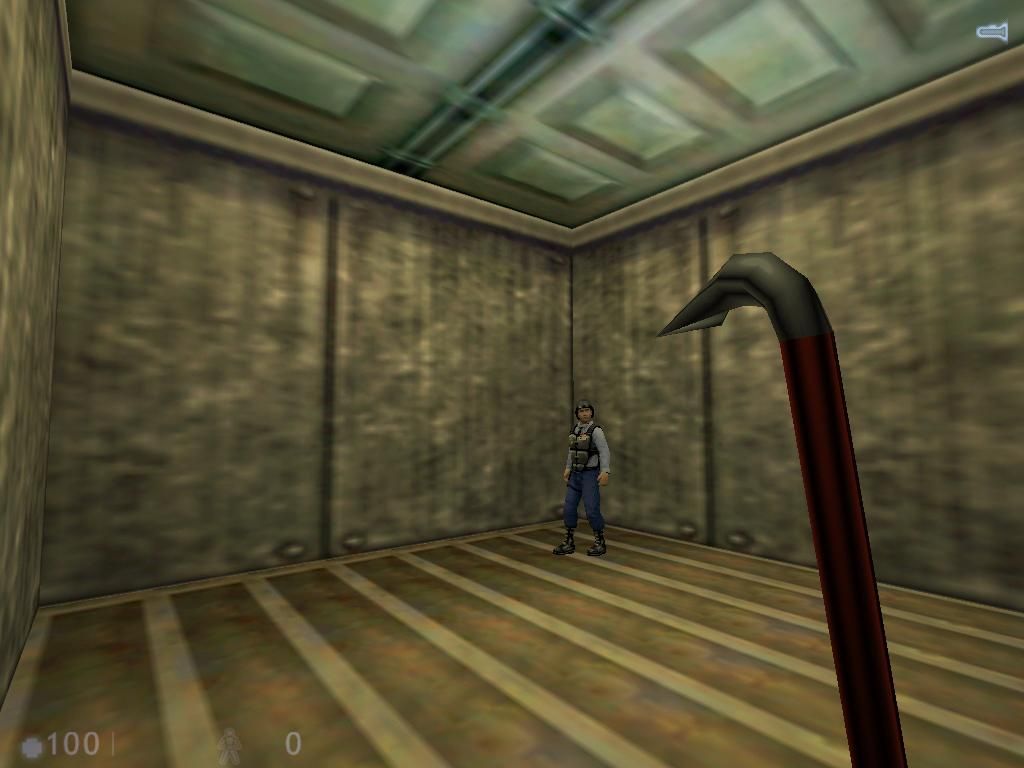
When you have everything looking right, hit go! and let the fun begin. Hopefully everything will compile correctly, and Sven Coop will start up, and your new map will load smoothly. It should look something like this: (I cheated, and used other textures, so your room wont look 100% the same sorry)
Hammer Resource Types
Before starting, you should learn a little more about the structure of the resources that Hammer and Half Life can use in a game. The Half Life engine can access and use a wide variety of file types and other resources. The list below is arranged by resource type, and each resource type includes a list of the sorts of files Half Life can use in that type, as well as a description of those files.
Project As mentioned before, the project is the total of your whole game and all its resources. A .rmf (Hammer Project) file at the top of your tree of game resource directories serves as a guide to Hammer. The .rmf file is a pointer to the rest of the resources for hammer and includes some of the information about your game resources. The rest of your games files exist in sub directories of the directory where your mod resides.
Directories The sub directories that Half Life use, are in your mods, folder, if you opened up your /half life /svencoop folder you would find allot of files, that you know not to remove, just in case you have to reinstall CS. Well each folder has different Resources in them. Sounds, have all the sounds you hear in game, such as the mini guns, spin up sound is the /svencoop /sounds /weapons folder, along with allot more sounds. The baby gargs breathing sound is in the folder /svencoop /sounds /babygar. The sniper rifle that you might like to hold, is in the /svencoop /models folder, while the player with the medkit is in the /svencoop /models /player folder. The wad files, if your don 't understand them yet, are in the root mod folder, such as afrikakorps.wad, is the afrikakorps mission set wad file, and that sits in the /svencoop folder.
Note: removing rescourse is not a wise idea, as this can cause you to have to reinstall Sven Coop. You can add folders for your map, if you use custom resources. Just check that you package your folders, and custom resources in your .zip when you make the map public.
Worlds Worlds come in two forms .rmf files and .bsp files. If you think of worlds as programs, the .rmf file is the source code: Editable and understandable by the user and hammer, but not executable. The .bsp file is like an actual program: it can be run in the game, but since its been “compiled” ( processed , in this case), the user can no longer modify it. The .rmf files are what you change and save changes to inside of hammer, and the .bsp file is the output of the ZHLT Compile Tools, which prepares your world to run in the game and optimizes its performance.
Textures Half Life uses its own form of texture, the .wad
file. Textures can be up to 8 bit images, although you can obviously choose to
make lower color textures. The .wad files also contain flags for additional
information used by the engine and the game. You can convert .bmp, and .jpg
files into .wad files by using a program such as wally http: //home.telefragged.com /wally /,
or qlumpy.
Expert users Note -With Steam, you can use 32 Bit textures, and as a
result, you will need to use Wally, to make a .wad from these quilty textures.
Sprites Sprites (.SPR files) consist of a series of .bmp files linked together as an animation with a set frame rate. They 're commonly used for animation 's and special effects such as smoke, or liquid droplets.
Sounds Half Life supports standard 8 bit mono .WAV files. You can convert high sound files, and the sound recorder 8 bit mono 's with gold wave http: //www.goldwave.com /a very useful program.
Models Models in Half LIfe are in a custom format, the .mdl file. This contains the mesh /geometry for the model and other information used by the game engine. You create these files in an external editor such as Maya or 3D Studio Max, then save them in the .mdl file format using a plug-in. You can also get your hands on a shareware program named milk shape from http: //www.milkshape3d.com .
Objects Also known as Entities , these are objects that programmers construct using code. Some of this code exists in the engine and doesn 't appear in the entity lists. However, many objects are created in code written for the specific game. These objects are called game objects (to distinguish them from the engine objects inside the engine code) and are stored in a file called a Game Data File or .FGD.
Prefabs A prefab is a collection of objects, both brushes and code objects that are stored in their own .ol files. Anything you make in a level can be exported as a prefab to make it easier to re-use later. Examples are benches, camera systems, hallways, doorways, and statues.
Creating Brushes to Fit Your Needs
Our first step will be to make a new world. Since we 'll be doing a bigger world than before, lets save it as “Big1”. Create it just as you did in the last chapter.
Also, we will want an appropriate texture for our floor. Go to the Textures drop down list and select any texture you want to use, you can also click the Browse button, and enter a key word, such as out, and chose a texture from that.
After you chose your Texture go to the Top view port (the upper right one). Look in the Status Bar for the Grid box, which shows the size of the grid blocks in the current window. Make sure that it says Grid: 64 , indicating a grid block size of 64 units.
 Tip:
The Grid is a way of organizing the
placement of objects, similar to a ruler. It keeps you from laying out points
totally at random and it allows you to measure the size of the objects you’re
creating and their relative positions
Tip:
The Grid is a way of organizing the
placement of objects, similar to a ruler. It keeps you from laying out points
totally at random and it allows you to measure the size of the objects you’re
creating and their relative positions
Using the grid makes for much more efficient level layout. When you build to the grid using standard units, your walls are more likely to line up properly and others can more easily understand your level just by looking at it. (If you chose to make your map open source at a later stage)
If your grid setting shows something other than 64, you 'll want to adjust the grid scaling. First, single click in the Top view port to make sure that the focus is in that port. Then, either use the Expand /Shrink Grid toolbar buttons or the OPEN SQUARE BRAKET ( [ ) and CLOSE SQUARE BRACKET ( ] ) keys on the keyboard to scale the grid up or down until its at 64 units.
While 64 units is a reasonable grid block size for laying out floors, walls and ceilings in indoor spaces, if you were working on a large, open outdoor level, 256 units might be a more manageable grid scale. Your goal is always to use a large enough grid to allow you to tell how big your current brush is going to be, but still small enough to create whatever detail you 're going to create.
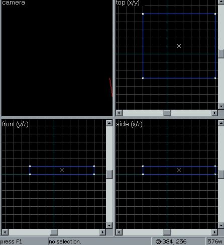
You 'll want a floor that 's about 512 units per side. That means you 'll want to make a square that 's eight grid squares on a side. Create one now, and you should get a brush that looks like the one on the top of that page.
 Now that you have a floor, the next step will be to use hammer to make
complex brushes, beyond the simple squares that you 've used so far. You 'll
also learn tips and techniques for good brush construction.
Now that you have a floor, the next step will be to use hammer to make
complex brushes, beyond the simple squares that you 've used so far. You 'll
also learn tips and techniques for good brush construction.
The simplest technique is to use hammers clip brush tool to build a brush that is close to what you want. While this tool doesn 't make it possible to instantly create anything , it speeds things up a lot, and makes your map have less bugs compared to vertex editing.
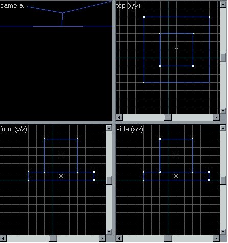
For the next step, select a new texture, though check its different enough from the floor texture to make a good contrast. Then, go into one of the horizontal views (Left or Front viewpoints). and make a block so that it rises 4 grid squares above the floor. Your block is now 256 units tall, and is about the right height for a tall and imposing support structure. Now, switch back to the Top view.
In the top view make your block 4 units wide so that it sits in the center of the map. Now you have a box box The next step is to click the Clip tool.
The clip tool is a magical piece of mapping tool work, as you can use it to make cliffs like in militia, or to make a simple ramp like in dust. This time we are going to use it to clip of the corners of a brush, to make it look like a support, or a smoke stack.
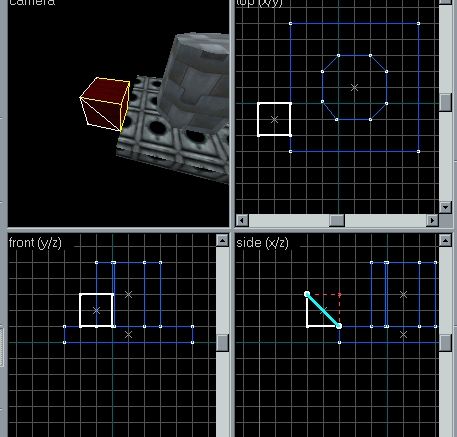
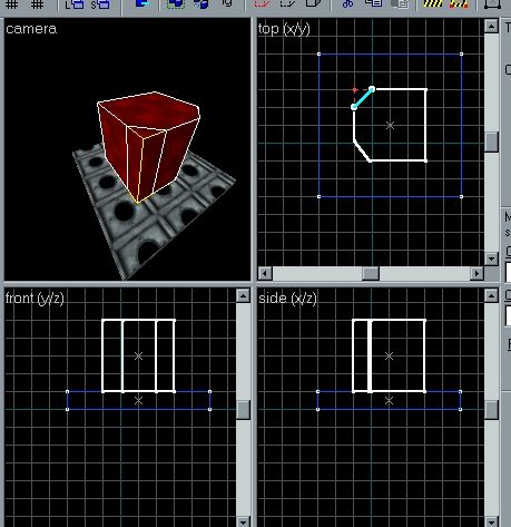 Make
the block active with the selection tool, then make the clip tool active, click
any where on the grid, and you will have the block will have thick white lines.
as show to the left. Now click and drag, and you will have 2 small round
handles, click one of them and al ine it 1 grid marker from the edge. Click the
second one, and aling it as show to the left. The area that is shaded in, in
the white lines is what stays, the area that is show in the red, is what is
chopped away. To make the clip, right click, and chose "clip
Object"or just press enter.
Make
the block active with the selection tool, then make the clip tool active, click
any where on the grid, and you will have the block will have thick white lines.
as show to the left. Now click and drag, and you will have 2 small round
handles, click one of them and al ine it 1 grid marker from the edge. Click the
second one, and aling it as show to the left. The area that is shaded in, in
the white lines is what stays, the area that is show in the red, is what is
chopped away. To make the clip, right click, and chose "clip
Object"or just press enter.
TIP: Pressing enter stops possible movement with the mouse, making your clip
sloppy.
Do this to the other 4 sides, to make the result look like then next screen shot
This is an example of an object that can be created quickly, and cleanly using Hammer but would require several steps in most other editors. However, the ability to create brushes this way does allow you to create brushes that hammer and Half Life cannot properly use in games -as some times you clip a wired angle, and the block, becomes concave, stooping your compile from working past that point.
 The Camera
So far, you 've only done small and simple things that haven 't required you to do too much with the Hammer interface, but now we will discuss one of the key elements that you 'll be using a lot -the camera.
You 've already learned to use the camera in the three 2D view ports. The 3D view is more complicated and very useful. Hover your mouse over the 3D view port (top left). Right now you should be seeing a very close-up view of the pillar you just made. Press the Z key and move the mouse around slowly. The windows camera moves in all the planes as you move the mouse. To move vertically, Horizontally, use the W, A, S and D keys.
Press the Z key again, and your back to normal design movements. Pressing the esc key while in Camera mode, will set the camera to the projects due north, or 0 degrees.
With these controls, you can move the camera anywhere in the map you need to see something. You can also see the object from any angle. For now, maneuver your view so that you can clearly see the column you created
There is also only 1 map tool that will work properly in camera view, and that is the decals tool. You can only use decals.wad decals with this tool, and we will discuss its uses later.
Right click on any design view port to display the Context menu. Use the commands on the Context menu. To change the to change the view that your camera presents, click the name of the view, and chose a new one from the drop down list. Its best to use 3D TEXTURED in 3d view if your video card supports Open GL.
3D Flat shading and wire frame display are useful for seeing how your brushes are laid out, since textures can obscure seams between two brushes, making some tasks difficult. These modes are also faster in some cases, so if hammer runs especially slowly on your machine you may want to use them to speed things up.
 More complex brush work
Now, switch back to the design view ports and add a brush that is 128x128x128 from the ground and looks similar to the figure to the left.
Now get the clip brush, and clip the brush so that you have a ramp, like the one on the left. This ramp, is very step, and would take a long time to climb if you had an AWP in your hand. As a normal rule for ramps 2x1 is a normal. Where the block is 2 units long for each unit in height. For roads, a 3x1 is better, where the block is 3 units long for each unit in height. When clipping, sometimes you might get an over sized texture. This can be cause from having the Texture lock (TL) hot key shift + L on, or its just how hammer wants your brush to look. if this dose happen, there is not much you can do to fix it, other then undoing that clip, and trying to re clip the brush, in most cases dose not work.
Selecting Brushes
To select a brush, left click on it, with the section tool, in any of the view ports, move your mouse over the brush you want to select. If there are brushes stacked on top of each other, hammer tries to pick the one it thinks you want. If a big brush is in front of a smaller brush, clicking inside the smaller one will select it even though the bigger one is “closer” to you.
One way of speeding up your work is to
select multiple objects or brushes at once. The primary way to do this is using
the ctrl + left click mufti select mode. If you mistakenly add a brush
to your selection, hold down the CTRL button and left click on it again to
remove it from the selection. It can be difficult sometimes to select the brush
you want, and you can accidentally select the wrong brush. Clicking an empty
part of the map, in any of the view ports de-selects all brushes, after which
you can select the single brush you want to work with. Be sure to use the
camera frequently to be sure that you don 't grab the wrong brushes. 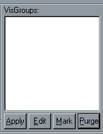
Another way to select a group of brushes at
once is by using a block selection, which can be used in any mode. Move the
mouse into the top view, then left click and drag out a rectangle that covers
the pillar in the center of the level as well as the ramp you added before. You
will see a white highlight that outlines the area you 're selecting. Once you
release the mouse button, all the objects under the highlight are selected. In
the case of brushes, a brush only becomes selected when the highlight touches
one of its corners, so you can select a brush that 's on top of a larger brush
without selecting the brush below it.
Lastly, you can use the Vis Groups to select and find objects by name instead of having to find them visually. To add a vis group click the object you want, then apply in the vis groups window.
Vis groups hide brushes, so its a good idea to only use them once you understand who to work fully with hammer.
Though vis Groups are useful on larger levels, where you may know what brush you 'd like to select, but cant easily jump to it to select it. In that case, you can then assign it, or a groups of brush to a vis groups to quickly find that brush you want.
Brush Power Tools
Even with hammers primitives and its wonderful clip tool, you still cant create all of the brushes you want in a single step. Hammer has three main tools for changing the actual shape of a brush: Hollowing, Carving, and clipping Mode.
The reason that these tools are in a section called “Power Tools” is because that 's what they are. While they are very useful tools, they are also very effective for destroying brushes, making your levels slower to process and slower to run, making bad designs worse, and not mention, cause major head aches for you, and your compelling software. As in carpentry, think twice before you cut. Be sure of what you will get before using these tools. Also, don 't forget about the undo ability in hammer if you do go wrong.
Using hollowing, you can empty the inside of a brush, like hollowing out a pumpkin. For a demonstration of how to use this technique, you can very quickly build a box around your entire level to contain it for processing. This is also known as a n00b box, as allot of new b mappers uses these boxes to stop leaks that the map might have had. Its bad because it causes high read speeds (r_speeds), slows down compile times, and can cause player drops, or server crashes.
Though to do it on non final compiles i 'll
teach you how to do it.
First, chose the a texture from the filter
"dirt".
Draw a square brush that surrounds the whole
level in the top view and make it 1024 units tall. That 'll make it large
enough to contain the whole level with some space left over. Now, with the big
new brush (and nothing else) selected, click Tools and then from the
tools menu Make Hollow from the Brush menu. When prompted, enter -64.
A -number tells hammer to make the brush hollow inside the brush, and not
out side of it. This value is the thickness of the walls of the brush, which
will be created around the brush. Then the original brush is deleted. 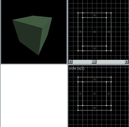
You 're probably annoyed that you 've been
taught to create rooms using the slower method of laying out each of your wall
brushes and ceilings by hand instead of just creating and hollowing cubes.
However, if you look at the created brushes, you 'll see that hammer created
brushes whose edges are beveled instead of straight. This is to fit them
together neatly with the minimum number of faces visible, although in some
cases hollowing can drive up the number of faces on your brushes, leading to
higher polygon counts inside your game. Also, because of the beveled edges,
hollowed rooms must be resided by moving vertices, instead of by moving whole
brushes.
Hollowing can be useful, especially when the bevels fit in with the design of your room, or are in areas that wont affect the rest of the layout. If you 're using it in an area of the map that you plan on changing a great deal, consider building your brushes by hand instead. Its usually neater even if it is slower.
You can also make your hollow box into world brushes by selecting it, and then pressing ctrl + u, which will un group them, and make them world brushes. But because of the beveled edges, hammer, adds even more pollys to them to make them normal world brushes, that can increase the read speeds.
Your next tool is carving , also known as CSG Subtraction . Its similar to hollowing and the two can even be used interchangeably for some purposes. However, as with hollowing, it can often produce unintentional results.
In order to carve a brush, first you need to create the brush to be carved. Next, you need to create a second brush that will serve as a tool to carve with . As you may guess from the name of the operation, the volume of the second brush will be subtracted from the volume of the first brush.
As an example, you can bevel an edge off of the top of your pillar to give them a little more of an interesting look. Select the ramp, Copy ( CTRL+C ) and Paste ( CTRL+V ) it, then move it so that it overlaps the outside edge of the pillar.
Re size the copied ramp so that its edge is a 45 degree slope in the Front view, then re size it in the top view so that it overhangs the north and south edges of the pillar a little. You should get a brush that looks like this:
The purpose of the overhang is to make sure that the brush cleanly carves the surface of the pillar. Its not necessary, but its a good idea. Hammer may occasionally create a bad edge or face when using carving, and overhanging a little helps to minimize the chances of this. If it does happen to you, use undo to back up and then try re sizing your carving brush to overhang the area where the problem appeared if its possible to do so.
If you cant overlap the carving brush for some reason, see the section on fixing damaged brushes later in this chapter. It includes techniques that might help you fix any damaged brushes that result. You may also be able to use splitting planes (which you 'll learn about next) to do what 's needed.
Notice that your carving brush only touches the pillar and not any of the other brushes in the level. That 's because carving with a brush cuts its shape out of any other brushes its touching. Make sure that your carving brush isn 't touching anything you don 't want to carve. You can select both the column and the carving brush, then use the Hide Inverse command on the Selection menu to hide brushes that are in the way. Then select any brush and use the Un hide Inverse command to bring them all back. Alternately, you can move the carving brush and the brush to be carved to an area of the level that 's open enough to avoid the problem and move them back when you 're done.
Once you have the carving brush in place (make sure only the carving brush is selected), use the Carve command on the Tools menu. Move the carving brush away from the column and look at the result. What you should see is that a new edge has been carved off of the column, leaving a large beveled edge. As with re sizing brushes, its a good idea to line your carve up so that any new vertices stay on the grid, although this is most often a problem for brushes you plan on doing more to after the carve. If you 're building chunks of rubble, you may not care as much about the results being on the grid.
This technique can be used with more complex shapes as well. If you stick a cylinder shaped brush into a wall to make a doorway or into a ceiling to make a window, you can create some very complex effects quite quickly. However, as with hollowing, your decisions on how to lay out brushes are very often better than the computers, and your cuts are probably going to be neater and easier to understand. The splitting planes tool, your next power tool, is designed with exactly that in mind.
Note: You might want to create some brushes outside the current map and try playing with carving for a little bit to better familiarize yourself with how it tends to cut before moving on. Try more complex carving shapes and carving multiple brushes at once. Be sure to watch the brushes that you get as a result. To more easily view the splits on your brush faces, turn off the textures. Click on the word Camera , and chose 3D Flat.
Flipping, and Turing Brushes
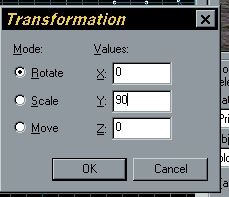
Sometimes you make a brush, but it won 't fill
the hole you want for it. The flip, and rotate options found in the tools menu
are what you need to do this.
To start, build a brush that is a cylinder with 8 sides (in the brush drop down list, chose cylinder under block) check the box has the number 8, and build a 64x64x64 brush (1x1x1 units).
Next click tools, transform, and in the resulting box, enter 90, in the box marked with the Y, this will flip your cylinder 90 degrees, on the y plane.
You can also use the drag handles in the view ports, by clcking the brush twice, though these often result in un predictable results, including concave brushes, in compile.
Advanced Texturing and Alignment
So far, most of the texturing that you 've done has been relatively simple, but hammer supports more intricate texture work as well, both on a brush by brush level and on a face by face level. You can see how to texture whole brushes, as well as how to texture single faces. You will also learned to select a texture off of a face without having to find it in the Textures list.
Even when you follow all the rules of good brush layout and level design, some textures don 't line up where you want them to be when you first apply them. Either the textures edges don 't line up with the edges of the brush, the only texture that has the symbol you want on it is too large, or a crate is rotated off the grid and its textures are not.
This section will show you how to scale, rotate, offset and flip textures. Get a good view of the main ground brush in the camera view port. Then select the Texture tool hot key shift + a
This tool has 6 different options detailed below
Lift and Select -The default Texture application tool option. This option lifts a texture, and also selects its face in 3d view.
Lift -the same as Lift and select, though it dose not chose the face
Select -the same as lift and select, though it only chooses the face
Apply texture only -applies the current texture in the thumb nail to the face, ignoring any custom values set in the options above
Apply texture and values -applies the texture and values to the face, with the currant thumbnail texture.
Align to view -aligns the currant thumbnail texture to the face,
with the currant view angels in the camera view. 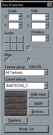
You can use the texture application tool in any
of the 4 view ports, though working in 3d texture view is easier to see what is
happening. You can also use the Texture Application tool, in free look mode, as
clicking an object will apply the currant option to that brush.
For instance, a texture may perfectly fit the brush but hang a little off center: say, 4 pixels too low and 8 pixels too far to the left. To correct this, you would add to the X and Y values. Setting the X value to 8 would move the texture 8 pixels across the face to the right, and setting the Y value to -4 would move the texture up 4 pixels on the face.
This isn 't something you want to use for all of your textures;its much better to build such that the bulk of your textures fall naturally along brush boundaries so that you don 't even need to think about texture alignment on most of your brushes. Its meant to be used for detailed, standout objects like crates, signs and display screens which are often set at odd locations and need to be exactly aligned.
The next control, the Rotation control is what you use to align a texture on a brush that 's been rotated. Perhaps you 've made a poster that 's hanging on a wall at a slightly weird angle of 17 degrees to make the room look a little unkempt. By applying a 17 degree rotation to the texture of the poster, you can get the poster to look as it should, properly lined up on the brush.
The next controls are the X and Y scaling controls. By default, these are each set to the horizontal and vertical size of the texture on the current face in pixels. However, by changing these values you can change the size of a texture in the world. By modifying just one of them (say, doubling the value in the U scale) you can stretch the texture. By doubling both of them, you quadruple the size of the texture on the brush. Lastly, you can flip a texture without rotating it by putting a negative value into either of these boxes. There are many cases where mirroring a texture can be useful: aligning trims on a wall, building a fake mirror image of a screen, and giving a clue to a secret door. The dialog also has two Flip buttons that allow you to do the same thing.
Finally, there are two check boxes. When you click the Texture Lock hot key shift + l , hammer will attempt to hold the textures aligned to the brush 's faces as they currently are. This allows you to move the brush around without the texture sliding around on the face. hammer will try to automatically update the textures’ offsets and even rotation to keep the faces. Although hammer doesn 't always make the right choices, for simple moves and simple rotations it can be faster than doing the math yourself.
Invalid Brush Types
Though we 've already talked
a little about invalid brushes earlier in this chapter and other chapters, this
section goes into a little more detail on the how and why of bad brushes and a
few ways to repair them. Not all problem brushes cause terminal problems, and
some of them are even useful under very specific circumstances (such as 1 sided
polygons). However, until you learn how to use them, you should always be sure
to avoid creating invalid or problem brush types. 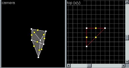
The first type is usually created accidentally.
Move to the Top view port and make a block 4x4x4 grid lines. Now chose the
Vertex tool, and make the block into a wedge. When asked to merge vertices,
click no. Now try to compile the map, (check to save first). The compiler will
try to compile, but come up with a box asking do you want t contuite, click no.
Don 't close the process window, but scroll up until you find the part that has
plane with no norm (near the top). This the error of an Invalid brush.
The brush in fact, not only is it flat, it has only has 3 sides, visible but has 4 true sides. What that means is that from one side its solid and has a visible surface, and from the other its completely transparent. The compiler will alert you if it finds one of these brushes in your level, and often you 'll wonder where it is. By clicking map, check for errors, and fixing each error in the list, your map should have less errors, but this brush is so bad, it has to be removed.
Working With Concave Brushes and Loose Faces
The best way to deal with concave brushes is to remove the totally. There are ways to save them, but by the time you saved the brush, it would have been just as quick to re make it.
Brushes also sometimes develop a loose face. If you try to move one face on a brush in and the rest of the brush doesn 't follow it, the face has probably been detached from the rest of the brush. This is rare, but its also easily fixed. Undo the move so that the face goes back where it was.
This technique can also be used to correct problems from a carve where one plane of the brush protrudes too far, another rare problem. Just move any misplaced vertices to where they should be attached and then join and clean them up as described above.
Another problem that can occur is brushes whose vertices don 't all land on the grid. Sometimes, a vertex that 's off of the grid slightly will be mis compiled due to rounding errors in the floating point math involved in processing the level for the engine. As a result, you may see gaps between brushes where two faces don 't line up as they should. Again, making sure that you don 't create brushes whose vertices leave the grid is the best way to prevent such problems. Care when stretching, carving or splitting brushes can prevent most of these problems, and you can correct them after the fact using Geometry mode.
These types of errors are especially common when you import terrain using the old style gen. surf program (version 1.0 and under). Most of the terrain sections will probably have vertices that are off of the grid. Usually, its possible to correct some of these by selecting all of the terrain brushes, and dragging it until it snaps to the grid. Some errors will often remain, but you can correct these by fixing the vertices of just the problem brushes and their immediate neighbors by moving these vertices onto the grid.
One last type of error occurs when two faces of different brushes occupy the same space. In such cases (a handrail sticking through a wall, two walls whose corners overlap), if the overlapping planes are both visible to players, the engine may not know which to remove. In these cases, it will leave them both. This results in a weird flickering display of both surfaces at once, known as bleeding, which is pretty unpleasant. You 'll recognize the effect when you see it.
The way to avoid this is to make sure that
where surfaces meet, they don 't overlap on surfaces where the player can see.
Don 't overlap two walls at the corner;just neatly join them.
Don 't run a handrail all the way through the wall;just end it where it touches the wall. Figure B presents the proper way to connect two brushes at a corner. Surfaces that the player can never see are always removed when a full Processor run is done. Luckily, that means you only need to worry about this issue in cases where both surfaces are visible to the player. Though if the hand rail has more then 4 sides, it can cause your read speeds to rise.
Lighting the Map
In our first map, we added a point light -this section will try and teach you how to make lights out of brushes known as texture lights, and how to use other lighting entities.
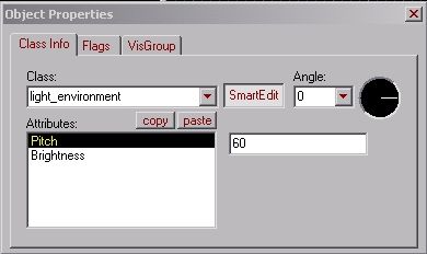 Environment lighting
Environment lighting is used most for
outdoor lighting, and well then you map must have a "sky", its a
brush with all faces covered with texture "sky". Then the light will
not come directly from entity, but from sky. To add a "Environment
lighting"to your map, you 'll need to add a point based entity named
"light_environment"to your map, you can do it same way you added
"light"but just select "light_environment"
"Pitch"There is not much settings, so its pretty simple to use
"light_environment". Important is "Pitch", the angle of
light, may have very dramatically results with trying different ##
there. And deal with brightness is same, as with point based light. a negative
pitch can add shadows.
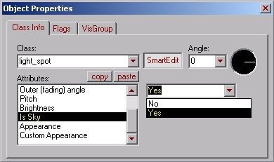 Spot lights
Spot lights are used when you want to make a spot light.
Or if you want to have effect when light is coming in form a window.
How to, well add a point based entity
"light_spot"to your map, to the place from where you want to light
come from, then open light_spot properties.
|
Target: |
target_1 |
|
Inner(bright)angle: |
20 |
|
Outer ( bright ) angle: |
20 |
|
Brightness: |
255 255 121 200 |
then add a point based entity
"info_target"to where you want the light go to. And from its
properties:
|
name: |
target_1 |
With these options I got effect like in previous pic, you may change them, like color, angles etc.
Also, you may use spotlight as a environment light, then just you cant use info_target, and you must specify the lights angle with "pitch"and "angle"options, also you must select "is sky"from its properties.
Texture lighting
Texture lights, all right you ask, why should I use a texture light, my point based entity lights are just as good, if not better. Well the truth is, you can use texture lights in any area and they will look good, as long as the light texture is in coordination with the textures around it.
An example could be, dust2 all those long light tubes are in fact texture lights, they set the map in to place, imagine what dust2 would be like, if there was a light reflection on the wall, but no where to show where the light cam from.
Also texture lighting shaves about 50 % off your RAD Compile time, compared to point based lighting
As I said there is 2 ways to add lighting to your map via point based entities or via textures, although the entity lights can be easily controlled, and support a wide range of effects such as you can turn them on or off at will, make them flicker, etc., it dose not look quit the same nor as good as textured lights. Rooms with lights and no light fixtures in them, such as a dust2 with no long light tubes look pretty crummy, and you also run the risk of an “Entity list too long” error. Trust me stick with texture lighting, it 's easier and cheaper, on both compile times, and map making times.
Using a texture light
Using a texture light is pretty simple, all you need to do is make a brush or a block, or even cover 1 face of an existing brush with a light emitting texture.
For example try making a solid covered with the texture called ~LIGHT3B on the roof of a room. When you compile your map it should be emitting a yellow glow.
How do I know what texture emits light or not?
How do you know what texture emits light or not? You ask, well this is simple, just open the lights.rad file found in the World Craft /Valve Hammer Editor folder or where your RAD program is e.g. C:\Program Files\Valve Hammer Editor with a text editor such as notepad, this list the textures that will give off light followed by the color of the light and finally the brightness e.g.
YELLOW 255 200 100 2000
Thus a texture named yellow, in any wad you use will emit light with a RGB Value of 255 200 100 (yellow), and a brightness of 2000
You can also make any texture you want emit light this way, all you need to do is just add in a new line with the name of the texture you want to emit light, the RGB value the light will give off (it dose not matter about the spacing between the name and the RGB value), and finally the brightness.
An easy way to set the RGB and brightness is to find a texture in the list that has a close match to the propriety 's you want the new listing to have and copy the values across
Ok, I know now all about texture lights, but -
1. My lights textures don 't emit any light
2. And my lights.rad file only has 1 listing or
is empty
Why?
Well that is a very simple fix, first check
that the texture is a light emitting texture, normally light emitting textures
start with a ~ e.g. ~LIGHT3B
Second go to the folder where your compilers
are, e.g. C:\Program Files\Valve Hammer Editor\ and rename the file “valve.rad”
to “lights.rad”, with out quote marks. When you compile check the process
window, at the part where it starts to perform RAD it says using text lights
from C:\Program Files\Valve Hammer Editor\lights.rad or something a long those
lines.
Q & A
Q. Do I have to distribute my lights.rad file with my maps?
A. No. The lights.rad file is just a file that world craft uses to compile your maps, the game dose not need the file to read the map or for you to play the map.
Q. Why do I have more face lights then I have light textures when I use light textures?
A. A brush normal has 6 faces;each face on a light emitting texture is a classed as a light by RAD.
Q. You said that my RAD compile would be cut in half if I used texture lights, but it 's taking me twice as long. Why?
A. It may be your computer system. Systems that are older, say a P 1 200, with 8 Meg of ram will take a lot longer because world craft /hammer needs to use the windows swap file, but if you use 256 Meg of ram on a newer system, such as an AMD Athlon 800, it will be cut by approximately half compared to point based lighting, due to the swap file not being need to be used as much. Also check the amount of texture lights, and how big the map is, this can make compile times take longer.
Working With Light Colors
 The
light colors property modifies the lights color. By default, the color of the
light is set to sun gold. But you can change this with the color options. The
screen shot on the left is the color selection pallet, and is where you can
chose the color for the light you are using. Abstract colors such as a purple,
or red, or not a normal light color, and should not be use, unless the map
calls for it.
The
light colors property modifies the lights color. By default, the color of the
light is set to sun gold. But you can change this with the color options. The
screen shot on the left is the color selection pallet, and is where you can
chose the color for the light you are using. Abstract colors such as a purple,
or red, or not a normal light color, and should not be use, unless the map
calls for it.
Lighting Half Life Worlds
These equations are from the "Lighting LithTech Worlds"chapter found in the Dedit.html documents in the SDK Patch 3 for AVP2PH, and AVP2. Though we can safely assume that hlrad uses these same equations. So please keep in mind that the LithTech, and Dedit names in this chapter, can be assumed as Half Life.
LithTech uses a combination of light maps and vertex lighting to light worlds. Light maps are textures generated by the processor at world compile time. Light maps contain ray traced lighting information for an individual polygon. Light mapping is used for all world geometry, along with world models, except for terrain. Terrain is lit by vertex colors, generated at compile time, and gourd interpolated across the polygons. Models are dynamically lit with normal lighting, attenuated with the equations below.
Below is the list of equations used by LithTech to calculate light attenuation. Light attenuation is the value multiplied by the light color to obtain the final lighting value for a vertex or light map texel.
Key: Att=Attenuation, d=distance from light, Lr=Light Radius.
Lighting Equations:
Light map & Terrain lighting (Default): Att=1 (d /Lr)
Custom Model lighting: Att=1 (d 2 /Lr 2 )
The Direct 3D & PS /2 model lighting use the function:
Att=1 /(A + B d + C d 2 )
Processor gives the option to use this same lighting model for light maps & terrain (marked Inv Quad Falloff in the Processor dialog). This lighting model generally yields more realistic looking lighting. (extra rad in hlrad.exe)
A, B, & C are constants: A=1, B=0, C=20 /Lr 2
I recommend that you always light your map with extra rad, as normal rad, can turn a good map bad.
Adding Sky to Your Half Life Level
This is one the simplest things that can be done in mapping.
Making skies are simple and easy to do. First, you must leave spaces in your level for certain brushes to fill up the gaps. It is best explained using the "room"method. As you all may or may not know, half life (and other Quake engine games) use the room construction method, where every area is a sealed environment linked to another environment through corridors, etc. Creating outdoor areas is simply turning the ceiling and some walls into the sky!
Creating skies is best explained through pictures, so here are some pics so you get the general gist of how and where to create them.
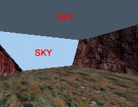
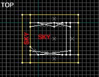
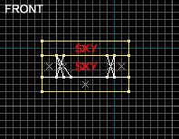
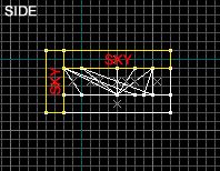
Remember that brushes that you want to have the sky seen on them must be textured with the SKY texture, which will be a tiny light blue box in your texture browser.
Once you 've sealed off your map with the SKY textured brushes, you are all set! Now you can specify a sky name in your map so you don 't get the default desert skybox all the time. Go to the Map button on your toolbar, then go to Map Properties in its drop down menu. In Map Properties you should see this:
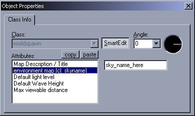
Where I put "sky_name_here"is where you specify the name of the sky you want to have shown in game.
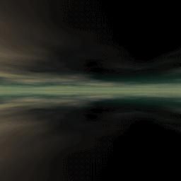
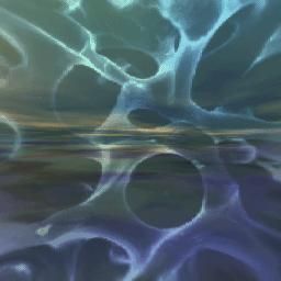
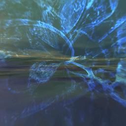
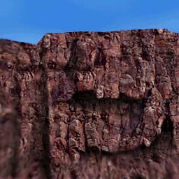
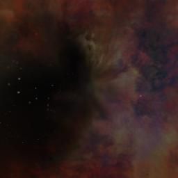
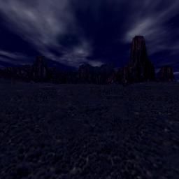
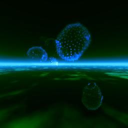
Here 's a list of the skies included with Half Life:
|
Sky Name |
Looks Like |
|
|
|
|
alien1 |
|
|
alien2 |
|
|
alien3 |
|
|
black |
|
|
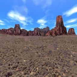
cliff |
|
|
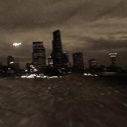
city |
|
|
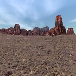
desert |
|
|
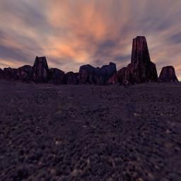
dusk |
|
|
morning |
|
|
neb1 |
|
|
neb2b |
|
|
neb6 |
|
|
neb7 |
|
|
night |
|
|
space |
|
|
xen8 |
|
|
xen9 |
|
|
xen10 |
|


If you 're mapping for a mod, it may come with new skyboxes for you to use. Be sure to check the mod 's skies directory, located under /modname /gfx /env /. The skies will be named skynamebk, skynamedn, skynameft, skynamelf, skynamert, and skynameup. The suffix denotes the location in the 6 sided box of the image. Use the prefix (the "skyname"part) in the Map Properties cl_skyname section.
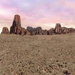
Once you specify a sky and everything else is done, you 're all set. Go compile your map and check out the sky!
Advanced ZHLT Compile Tools Use
ZHLT ( HLCSG.EXE, HLBSP.EXE, HLVIS.EXE, AND HLRAD.EXE ) is a separate executable from Hammer itself that is used to pre-process your level. Pre-processing a level is a great deal like compiling code. You take the human readable version you constructed and turn it into a machine friendly and heavily optimized version for the computer to use. The computer doesn 't have much use for your version, and you cant do very much with the computers version. You must process your level in order to run it in the game.
In Half Life, the human version of your level is stored in an .rmf (Resource Media File) file that is readable by hammer. It contains all of the brushes in the level as you laid them out, references to all the textures needed by the level, a list of all its entities and any other information about things you 've added to the level.
The computer version of an .rmf file is a .bsp (Binary Source Project) file. .bsp files have the same name as the .rmf file they were compiled from aside from the extension. Thus, if you built a level called “Level01.rmf” and compiled it, you would get “Level01.bsp” as a result. Unlike the .rmf file, the .bsp file doesn 't contain all your brushes as you laid them out. It also does contain some things that your .rmf file does not.
The first difference in a .bsp file is that the brushes in it have been broken down, digested and reassembled so as to optimize them in number and in layout for actual game play. Any polygons on the outside of the level or in areas that the player will never be able to see are stripped entirely away. The remaining brushes are all split up at each point where one brush touches another until nothing remains but convex shapes. You can read more about this process in the section below on optimization, as well as how to see the splits that result.
Another difference in a .bsp file is that things are now arranged as a series of hulls or visibility leafs , which are half life 's way of sorting out the areas within the level to determine visibility, as well as the connections between them. Between these two factors, a map inside a .bsp file and the same map in an .rmf file would be vastly different if you could open and compare them.
Another addition in the .bsp file is lighting data. Although you get a small idea when you become more advanced in hammer of each lights effects, the actual intersections and combinations of each light don 't get calculated until the level is processed. All of that data is then added into the .bsp file, mainly in the form of a second layer of textures for all brushes that are light mapped.
Last, there 's the addition of visibility data. The ZHLT Compile tools namely HLVIS.EXE builds a list all points in the level that specifies which areas can possibly see into which other areas. This is an important step because it vastly speeds up all but the smallest levels by cutting out of view any brushes that the player doesn 't need to see. As an example, if the player is standing in a small room on one side of a hallway and a doorway on the other side of the hallway leads into a large room full of boxes, the Processor might determine that there 's no way for the player to see into the large room without moving a substantial distance. It will therefore remove the large room from the visibility list for the small room. The engine will therefore not render the large room if the player 's in the small one, freeing up cycles when the level is running.
If this sounds like a time consuming process, that is because it is one. Compiling a large level completely with all optimizations turned on can take hours, or days. Quick compiles can sometimes take as long as 30 minutes, although generally the time is much less. However, ZHLT Compile tools gives you fine control over all of the steps in the compile, and by changing what gets processed and how thoroughly you can choose between a highly optimized level that 's ready to ship and a quickly processed level when you want to quickly check your results.
There are a few settings you will want to know about for all compiles. and for that you should down load Nemeses Batch Compiler, that is well detailed. You can get the Batch Compiler from http: //countermap.counter-strike.net /Nemesis /.
After you install the batch compiler, set it up as you would for the build tab in hammer (see chapter one) through the Options, Set Up menu. Some programs might not be on your computer, such as the Master, or net vis, don 't worry, as these where tools designed for internet use, and the servers that hosted the internet compiles have gone down due to lack of service.
One you have set up, Batch compiler has 10 tabs of what are:
CSG is the first thing that the compiler dose, it has these flags, and what each one dose:
nowadtextures -include all used textures into bsp. This option is obsolete by -wad include and is only left in to retain some backwards compatibility. This flag dose not work, so use the wad include option, its much cleaner as well.
wadinclude -place textures used from wad specified into bsp. This option will cause csg to include used textures from the named wad file into the bsp. It does partial name matching, is not case sensitive, and can also match directory names. If multiple includes need to be done, -wad include must be specified multiple times, once for each include. Only textures actually used in the map are included into the bsp. You can add unto 5 wads, with Batch Compiler
noclip -don 't create clipping hull. Half life like Quake, has 4 hulls, 1 visual hull and 3 collision hulls. This option disables generation of the collision hulls for a small savings in compile time. Note that the world will not be solid at all (everything will fall into the void) with this option set.
onlyents -do an entity update from .map to .bsp. This option will take the entities from the .map file and update them into the bsp file. For the most part, entities can only be edited. Adding or removing any can reorder the other entities which frequently breaks brush based entities, especially triggers.
noskyclip -disable automatic clipping of SKY brushes. By default hlcsg will CLIP all SKY brushes, as well as remove all non sky faces on the 'inside ' of a sky brush (which eases up vis time, and improves some time and memory usage in rad as well).
tiny -minimum brush face surface area before it is discarded. Tiny brush faces are outright removed. The current cut-off is 0.5 square units. It is dangerous to drop faces in this manner, as the BSP tree for the world can be unusable, or generate leaf portal errors or hall-of-mirrors vis errors.
brush union -threshold to warn about overlapping brushes. This option is a mappers debugging feature. The value passed in is a percentage (0 to 100) of overlap of two brushes before a warning is printed. Starting with a high value (95+) is a good idea, as going too low to start can print hundreds or thousands of messages. The brush numbers of the intersecting brushes and the percentage in which they intersect each other is displayed for each occurrence. This option is off by default as it dramatically slows down hlcsg to do these calculations.
hull file -Load a custom hull file. Loads a custom set of hulls for the collision hull generation. The file is composed of 3 lines of 3 white space delimited numbers. Each line is an X Y Z size of the bounding box it is for. Only specific mod authors and their mapping teams should ever worry about this feature.
BSP Is the second thing the compiler dose, and has these options
leak only -Run BSP only enough to check for LEAKs. If you already know a map has a leak, this is a good option to just save some time in hlbsp and just generate the pts file.
subdivide -Sets the face subdivide size. Faces in Half life are subdivided by this value (in units). The default and maximum are both 240, and it should never need to be set lower (as it just increases r_speeds)
maxnodesize -Sets the maximum portal node size. This option tweaks the maximum size of a portal node. Setting it smaller will bsp the world into smaller chunks at the cost of higher r_speeds, but it can pay itself back in many cases with making vis either faster, or more accurate, or both.
notjunc -Don 't break edges on t junctions (not for final runs). This is a development /debugging option that should not be set in normal use
noclip -Don 't process the clipping hull (not for final runs). This is a continuation of the -noclip option in hlcsg. In this case it tells hlbsp that hlcsg was compiled with -noclip and to not attempt to BSP the collision hulls as they are not present in the bsp
nofill -Don 't fill outside (will mask LEAKs) (not for final runs). This step causes filling to not be performed, which will cause all the faces on the outside of the map to not be discarded. It is probably a bad idea to rad a map that has been compiled this way, though vis should run normally.
Visibility makes the visible matrix as explained above, it runs third and has these options
fast -Fast vis (NOT FOR FINAL COMPILES). A fast vis is handy for running around in a developed map without dropping polygons. However r_speeds will usually be pretty bad, as well as epoly counts. The map can still be lit with hlrad, however its quality and compile time will both suffer as a result. Maps should regularly be compiled without fast vis, as fast vis can mask a sudden increase in normal vis compile time.
full -Full vis. This option enables extra calculations during vis, which help reduce the number of vis errors in a map over a normal vis. The speed hit is approximately 30% over a normal vis. r_speeds will generally be the same, though lower in some areas, and higher in others (primarily due to vis errors being fixed)
I have not used this tool, so i can 't say much about it, sorry
Master servers are dead, and i personally have never used it
RAD Is the lighting of the map, its run last, and can be the most time consuming part of a compile. It has these options. If you want to see each option is use, go to http: //ammahls.com /resource /rad /index.html
sparse -Enable low memory vis matrix algorithm. The original vis matrix algorithm was limited to 65535 patches due to its design. Its memory usage also grew exponentially with the number of patches (patches * patches /16 bytes). This option enables a compressed vis matrix, which at the cost of extra CPU time, breaks the 65535 limit, and also uses about 10% of the memory the vis matrix would.
nomatrix -Disable usage of vis matrix entirely. As the sparse code does some compression, it requires a lot of thread synchronization and does not scale well past 2 CPU 's. The -nomatrix switch was added to address this. However the addition of 'opaque brush entities ' starting with ZHLT 2.2 hurts the -nomatrix method 's performance quite a bit. There is no vis matrix in this method at all, so it essentially reduces the memory requirements to zero for that structure.
extra -Turns on 9 point over sampling for lighting, making it look much better.
bounce -Set number of radiosity bounces. This option sets the number of times light bounces in the radiosity pass. By the time the code gets to this point, all the data is pre computed, and extra bounces are very fast. It will make the shadows less harsh using more bounces, but can help light up dark areas much more naturally.
ambient -Set ambient world light (0.0 to 1.0, r g b). This option sets a minimum light value to every face so that nothing comes out pitch black. The values are red green blue, scaled from 0.0 to 1.0
max light -Set maximum light intensity value. This option can be used to cap the bright spots, if you want a map to come out darker overall.
circus -Enable 'circus ' mode for locating unlit light maps. This is a debugging option, which will cause all black pixels in any light map to be set to a random full bright color. It only looks at the direct lighting to make this determination, and ignores any bounced radiosity data for making this determination.
nopaque -Disable all entities using zhlt_lightflags 2 to block light. Using opaque entities slows rad down, and using this option is useful for doing quicker non final lighting compiles.
smooth -Set smoothing threshold for blending (in degrees). By default hlrad uses Phong shading on all faces. If the angle between two edges is less than this value, it will be shaded with the Phong smoothing code, otherwise it won 't.
chop -Set radiosity patch size for normal textures. Each face in the world has a grid projected onto it, and chopped up into a rather coarse set of sample points. These points are patches, and are what hlrad uses to do the bounced lighting calculations. A higher chop sacrifices quality for both speed and memory consumption of hlrad. A lower chop increases the quality at the expense of speed and memory usage.
texchop -Set radiosity patch size for texture light faces. Texture light faces are chopped with a different granularity than the normal faces, primarily so that the lighting looks good. Generally it should be half of the chop value. Adding -extra to hlrad will automatically divide this value by 2 at runtime.
notexscale -Do not scale radiosity patches with texture scale. By default, hlrad will take the texture scale and apply it to the chopping grid which is projected onto it. This option turns that off, and almost always increases the number of patches in a map as most maps have many walls scaled up to 2 and 3.
coring -Set lighting threshold before blackness. This value controls how much light it takes before a surface will be lit with a non black value.
dlight -Set direct lighting threshold. This option is similar to -max light, except that it re normalizes the direct lighting values instead of clipping them if they are too high.
dscale -Set direct lighting scale. Due to a bug in the original version of qrad, the direct lighting layer was added into the final lighting twice. The correct thing to do is only have it in there once, but at the time too many maps had been created with this assumption and it was left in there. This has been corrected as a command line switch, to scale the direct lighting by.
Using the value of '1 ' would generate the most correct looking maps. However, since this is configurable it has a few other uses. Using a value of '0 ' will remove the direct lighting completely from a map and it will only be lit with radiosity lighting. This ends up 'opposite ' of -bounce 0, and can be used to check the radiosity lighting for glitches. Using larger values, like 3 or 4, cause extremely harsh direct lighting relation to the shadows and might be of use in desert or arctic maps.
nolerp -Disable three multi point interpolation for radiosity patch blending, use nearest point sample instead.
fade -Set global fade (larger values=shorter lights). This value adds in an artificial factor into the normal (1 /dist * dist) inverse square falloff calculations, by multiplying the denominator of the scale by the fade value. Point lights can set their own individual fade and falloff values, which override any global setting on the command line. These calculations only affect the direct lighting layer, as the radiosity pass always uses plain inverse square falloff.
falloff -Set global falloff mode (1=inv linear, 2=inv square). This option can change the normal inverse square falloff of lighting in the direct lighting layer with inverse falloff.
scale -Set global light scaling value. This option scales the final light values right after the direct lighting layer is added to the radiosity bounced lighting layer. Low values make the world darker, higher values make it brighter.
gamma -Set global gamma value. This option also occurs after the direct and radiosity layers are added together, and a global gamma correction is calculated and applied to the lighting before it is finalized
sky -Set ambient sunlight contribution in the shade outside. Many faces have line of sight to sky, but fall in the shadow of some other object. This option affects how much of the normal sky lighting is put into the shadows.
lights file -Manually specify a lights.rad file to use. A single .rad file can be added to the compile manually, in addition to the defaults of lights.rad and mapname.rad
noskyfix -Disable light_environment being global. ZHLT 2.1 added a simpler more manageable system for light_environments. The new behavior is that a map only needs a single light_environment entity to light up all sky everywhere. The placement of the entity no longer matters. The -noskyfix option turns this feature off and enables the original code which require multiple light_environments to properly light up an outdoor area.
incremental -Use or create an incremental transfer list file. This is a handy option for tweaking lighting, especially on slow or lower memory machines. BuildVisLeafs, Make Scales, and Swap Transfers can be skipped entirely on subsequent runs of hlrad. Note that geometry must not change, but lighting can. Using the incremental file requires a simple but important procedure:
First hlrad is run
normally with -incremental. In addition to the map being lit normally, it will
generate an, incremental file, which is essentially the transfer lists dumped
to disk. Lights can be changed in any way (moved, brightness changed, color
changed, etc.).
Update the entities in the
bsp with an hlcsg -onlyents compile. Re-run rad normally again with the
-incremental switch.
The exact same options for
-extra, -chop, -texchop, -notexscale must be used on all the runs of hlrad. All
the other values may be tweaked.
dump -Dumps light patches to a file for hlrad debugging info. This is a developer option for zhlt, to dump out the patch data generated by the chopping /subdividing and make sure it looks all right.
This imports or exports an entity list with mapname.ent it can be edited, and then reimported back into the bsp, if some things like a light don 't appear to be right in game.
texdata -Alter maximum texture memory limit (in kb). Half life was built with a 2 Mb texture limit, as was Opposing Force. The ZHLT default limit is 4 Mb. Even 4 Mb can be a bit much, when combined with model textures, skies, hud graphics, and more. This is especially true of people with older cards (Voodoo 1 and 2 's, etc.).
chart -display bsp statistics. This option will cause the program to print out the bsp statistics right before it writes out the bsp. It is most handy to do -chart with hlrad and hlvis at the end of the compiles. The ripent program will always displays the chart.
low /high -run program an altered priority level. Setting the priority of the compile tools to -low is very handy, as you can multitask and do other things without really feeling the drain of the compile programs on the system, provided there is enough memory for the tools and the other programs you use.
nolog -don 't generate the compile log files. This option just disables the generation of the .log and .err files which are normally generated whenever the compile tools run.
threads -manually specify the number of threads to run. This option is generally only necessary on the non windows versions of the tools, where there is not a standard way to detect the number of processors in the system and auto set the value. It can be manually set on windows machines, primarily if you wish to use fewer threads than processors.
estimate -display estimated time during compile. This option replaces the 10...20... style progress indicators with a estimate bar with some estimated completion times, as well as the exact number of the current job and how many jobs there are to do. The three different times remaining factor in varying amounts of historical data to guess how much longer it will take to run. It is good for a ballpark figure, but frequently not much more accurate than that.
verbose -compile with verbose messages. Many of the tools have 'minor warnings ' and informative messages which are displayed when verbose mode is set. As the ZHLT 2.x series develops, many of the developer specific settings are being moved to developer messages, while the mappers related messages will remain as verbose messages.
noinfo -Do not show tool configuration information. ZHLT 2.1 added a configuration display for each of the tools as they run, to display the current settings for all configurable options as well as their defaults. This sometimes causes problems with other programs, most notably when compiling within World craft, it likes to crash when too much stuff scrolls into its compile process window.
dev -compile with developer message. Internal ZHLT debugging messages have been slowly added to the tools. This variable sets the 'level ' to display. In order (starting with 0 and going up) : Off, Error, Warning, Info, Fluff, Spam, MegaSpam. Generally this option should never be used except at request, to diagnose a compile problem on an end users machine.
These options let you remove certain rubbish
files after a compile, and not fill your hard disk with unto 30 megs of these
files.
Check all the recommend boxes -and leave all
the un recomned boxes blank.
This lets you set up the Half Life section of the compile, including the MOD To open once couple has finished, and other options, hover your mouse over each options to get a tool 's tip in the bottom of the screen explaining what each option dose.
After you have seen, and chosen what you want your compile to do, you need to export your .rmf file to a .map in hammer. The .map file is much like a .rmf file, but its a unervisaly reconigsed raw map format. To export your project in hammer to a .map, click File , and then click Export To .map.
Once you have exported to the .map, in the map location line at the bottom of the Batch Compile, click the browse button "..."and search for where you saved your .map file.
After you have your .map file set, check the
CSG, BSP, VIS, and RAD Boxes, along with HL, BATCH, and SHARED. The click
compile.
A dos window will pop up with your compile in
it -and once the compile has finished, Half Life will load with your compiled
.bsp map, and and also show you the compile log, for you to check over, if you
had bugs in your compile.
Types of Compile and Their Advantages
The first type of compile is the quick compile. If your level is under heavy construction, hasn 't been sealed and you only want to look at a few changes you made entities or brushes, this is the type of compile to do. In this case, you only care that geometry is built so that you can look around. You must set CSG , and BSP . You can also, take some lag out by using a Fast VIS , but leaving vis unchecked is good in most cases.
The second compile is a more thorough (although not full) compile. This is used when you want to check the read speeds (r_speeds) but don 't care about lighting. Set the BSP, CSG, and VIS to run, but also check the Full Vis box. This compile would take longer to build your map, but will have the proper VIS Matrix. Full vis can also fix some brush errors, though some can still seep through VIS.
Next is the full compile. Check all the options in the normal compile, but also, check the RAD , and the Extra RAD check box as well. This is the most time consuming compile of the lot, as it fixes many bugs, and also adds all your lights.
Its always a good idea to restart your computer before atempting a normal, or full compile, because the more RAM that is free, the faster your compile will run. The SWAP File, can make compiles run at 1 /2 speed making your total compile time double. So the faster your computer, and the more RAM You have can speed your compile times up.
Once you actually run the compiler, the
dialog will change to a log window and a display of progress bars showing
compile progress. If you read the log window you can learn a lot about how the
level is being handled.
If you get an error during compile, then please
check the errors appendix at the end of this page.
Optimizing Your Level
Its actually fairly easy to make a gorgeous Notre Dame-scale cathedral in hammer. Once you know the basic controls, you can pretty quickly lay out the brushes, apply the textures and add in the lighting necessary to make such a structure. However, it is also extremely easy to build a level that:
- Will not compile
- Will take far too long to compile
- Will run poorly in the game even after a full optimization
This is truly where the science of level design begins to take a back seat to the art. Though there are some basic rules and a lot of guidelines to optimizing levels, the best way to learn good optimization techniques is to experiment and to carefully observe the results you get inside your levels. You must think about optimization right from the moment when you first begin designing your level, and you must watch the performance of your level every step of the way as you build. Unlike any other computer art product, computer games are rendered in real time , and this restricts you substantially in what you can get away with in your levels
Factors That Cause Levels to Bog Down
Levels can become bogged down for a number of reasons. The first of these is high polygon counts in a scene. Even a simple empty room that has only walls, floor and ceiling can be made up of several hundred polygons. In order to apply lighting and tune the levels performance, the brushes that you make inside hammer are broken down, juggled around and reshaped by the ZHLT Compile Tools as it builds the in game .bsp file out of your .rmf, or .map file. As mentioned above, this process is one of the reasons why you cant edit a .bsp file in hammer. To measure the polygon counts in your game, you use the r_speeds 1 console command. As a general guideline, the game designers for Half Life kept multiplayer levels to around 400 World Polygons (W Polly) in general on multiplayer levels and 500 -600 or so for single player levels where frame rate was not as vital. Its important to perform some tests, or ask around, what the r_speed levels of today are. Also keep in mind that some mods, require your levels to be under a set number of w_polly.
Lighting a level via light mapping requires that large brushes be broken down into smaller chunks. This usually happens along texture boundaries. Thus, if you have a large room with a 64x64 floor texture, the floor may be broken up into dozens of 64x64 chunks when in the editor it is shown as a single brush. The reason this is done is to create the light map textures, which give the floor lighting. In the case of a moderately large room, this may add 200 polygons to the scene, but in some very large rooms it can add 400 or more polygons. Its important to take that overhead into account.
There are ways to reduce this press somewhat. The first is to try to break up large spaces so that only some of the space is visible at a time. The second, useful in outdoor areas without great ground detail, is to scale up the texture on the floor. Often, a 64x64 dirt texture looks acceptable if scaled up to 128x128. In some cases it even helps give a sense of scale to the outdoor room. Its important to test this technique yourself and decide whether or not you like the result.
The second cause of high counts is complexity. Its very hard to resist the urge to put every detail into your geometry instead of using textures to create detail. However, it is much more expensive to add detail using geometry than it is to simply detail through tricks of the eye, lighting and texturing. Avoid nonfunctional detail that can be added through textures like molding /trim, curlicues, grooves and bumpy surfaces. A level designers art is figuring out how to imply detail. Ask your texture artists to build a grooved surface or the face of a curlicued building ledge (or google img search some), and then apply that texture to a simple flat surface. Use as few sides as you can get away with on your columns and carefully consider how to build each shape with the fewest polygons.
Another typical cause of high counts is intersecting brushes. Every place where one brush touches another, the processor splits the touched brush in order to remove the hidden sections of each brush. However, this can drive counts up very significantly. A large, square room that 's normally lit would be subdivided into a simple grid of square brushes. If you place a square column in the middle of the room, the rooms still split along a square grid, since the splits around the base of the square column run parallel to the grid of splits made for lighting. However, if you put down a 12 sided column in the middle of the room, split lines run out from each of the 12 vertices that make up the base of the column. These lines disrupt the even pattern that existed before and scatter new brush splits throughout the room. You can observe this by using the r_drawflat 1 and gl_wireframe 2 console commands.
The best way to avoid this problem is to carefully pre plan before adding details in areas where their effects will be drastic. Also, in many cases such as light fixtures and some columns, you can build your fixture and then move it 1 to 4 units away from the surface it would normally be touching. That prevents the split, and in many cases the player will never notice the difference. You must be careful using this technique, however. If you place a light in the right location, it will give away what you 've done since the lifted object wont cast a proper shadow.
Another issue that increases your polygon counts in a room is visibility leaks. To explain, the computer and the player see the level in different ways. The player cant see anything that 's behind a solid wall or any solid surface. However, the computer always looks just a little bit ahead and pre draws some objects that may not yet be visible to the player. This is for two reasons: One, the computer estimates cautiously when it decides what the player will be able to see. Two, the computer pre loads some geometry that it thinks the player may soon be able to see in order to spread out the press of loading the polygons and textures.
This usually comes in the form of a wall or other fixture in the next room that adds to the poly counts in the current room. Sometimes the increase in counts makes very little sense. You can have a very small room without any real detail such as an entryway with the polygon counts of a much larger, more detailed room. If you look around in a room like this, you can almost always find either a hallway into another more detailed room or a leak to the outside of the level.
Troubleshooting Visibility Leaks
The useful console command point file comes into play when troubleshooting visibility leaks. What point file dose, is shows your a dotted line from an entity in the map, and will go through a wall, roof, ground, or such. Most of the time the leek is cause where the point file goes through the wall, though entities such as info_nodes out side the map will cause the leek to be appear because half life can not link that entity to the inside of the world.
You can break visibility between rooms most certainly using a corridor with a pair of 90 degree turns in it. A U turn should totally cut visibility, and an S turn with the proper length of corridor in between the two turns will almost always work. Below that, controlling visibility becomes an art. Often, you will be amazed by what the engine decides you can see from a given point. Its important to carefully walk your level and watch polygon counts for this reason. You can also use hint brushes though i won 't tell you how to use them, as they are very complex, and i don 't get how they full work yet.
Note: If you haven 't done a Full Optimization compile on your level, you cannot rely on the visibility or poly count results you obtain. Full Optimization cuts down counts far, far more than a Fast Approximation does. Similarly, if you don 't compile with optimization turned on at all, your whole level is visible from all points, leading to counts that are much higher than they will be after optimization.
In order to increase your chances of blocking off line of sight between areas, there are several things you can do. First, make use of kinks in between areas as described. Second, make sure that walls extend from the floor of a room to its ceiling. Third, make sure your walls fit snugly together. Fourth, keep the number of connecting doors, windows or vents between rooms as low as is reasonable so that you can more easily troubleshoot. Fifth, treat your outdoor areas in the same fashion, dipping your sky brushes down like a ceiling to close off one region of the outside from others. Use hills, hedges and tall buildings as walls to reach up and touch these sky brushes, thus completing the seal.
Plugging Leaks
If your level does develop a leak, you can use a leak file generated by the ZHLT Compile tools to help find it. Once the ZHLT Compile tools makes its leak file, load it into hammer using the Map menu to select Load Point File. This helps you to follow the path that appears until you find the hole.
Plugging leaks is important for three reasons. First, leaks can cause parts of the outer shell to be visible inside the level, unnecessarily increasing your counts. Second, leaks keep the levels outer shell from being removed by ZHLT Compile tools, increasing the size of the levels .bsp file on disk. Last, if ZHLT Compile tools has to do visibility calculations for the outer shell, it will take a great deal longer to complete. It pays to plug your leaks.
Another concern is a factor called overdraw , which is the number of polygons drawn on screen that are actually out of the players view behind other polygons. This is related closely to the visibility optimizations referred to previously. You can often find high levels of overdraw in rooms with lots of detail: columns, low walls, complex fixtures and cracks can all lead to overdrawing. Overdraw in a scene is measured using the r_speeds 1 console command. In the development of the game Half Life , for instance, values of 400 -600 here were considered acceptable and values of 800 -1250 were danger signs. Once again, testing on your target platform to obtain figures for your own game would be wise.
Besides geometry related factors that may slow down your game when its running, you can also get significant slow downs if you use too many textures or several overlarge textures in a scene. Even in the age of AGP, if you use a 512x512 texture for everything from tiles on the bathroom floor to murals to the name plate on a door, the game will run more slowly. As with many problems, this is best addressed in the design stages rather than in the testing stage.
You should try to resist the urge to use the largest texture possible and instead work to find a balance between a texture that looks good and is small in size. Objects that wont get much scrutiny like floor /ceiling tiles, wall to wall carpets and grass should usually be given small textures. Objects that the player will focus on (view screens with data, pictures, signs) can use higher resolution textures. The console command impulse 202 provides information on textures for help in troubleshooting.
Entities can also affect game performance. If you build a huge particle fountain that creates 1000 particles every second with a decay time of 10 seconds on each particle, the engine is going to be very busy keeping track of the particles. Likewise, large, moving objects such as props made from World Models can slow the engine down as it tries to manage their physics.
Character models and AI can also affect frame rate. A level that runs fine with just the player on it can bog down seriously when two very intelligent AI enemies are added to it. Likewise, a Boss character with thousands of polies in her character model will slow the engine much more than a minor character with just a few hundred. Be careful how you code, design and place your AI. Also, be sure to test the results to make sure you haven 't stressed the system too much.
As mentioned before, optimization is more art than science, and it takes practice. The warning signs of trouble you should always heed are low frame rates, high polygon counts in a scene, and sudden jumps in the length of time it takes to process your level. Any of these should make you take notice. Immediately backtrack and figure out what has caused the issue. Even if you don 't do anything to correct it at the time, performance issues are almost always easier to fix if they 're identified early. It is heartbreaking to have to discard a level that is completed but completely unworkable, and you will do so if you don 't pay careful attention to optimization throughout the construction process.
Legal
This page is design for use for Hammer Editor 3.4, and Hammer Editor 3.5 Beta some parts may have errors. Some parts are used with out permission. This document was designed for use with WON Half Life, and as such, Mappers Using the Steam Platform, will need to find a substutie for seting up there Editor.
Mirrors of this page must have links to this site, including my email [email protected] .
I support Planet Ark paper reduction, so please print on both sides of the paper.
amckern
PS. If you still need help, sign up on the Sven Coop map forums at http: //www.svencoop.com /forums /, or email me [email protected] , or AIM me on amaperman.